Architectural Drawings: The Main Types Explained, How to Read Them, and What AI Still Gets Wrong

Architectural drawings are the scaled drawings that describe a building: a site plan for where it sits, floor plans for the rooms, elevations for the outside, sections for how it is built from foundation to roof, details for how the pieces meet, and schedules for doors, windows and finishes. At the end of design those sheets are joined by the structural, mechanical, electrical and plumbing sheets, and the whole package becomes the construction drawings, which most people call blueprints.
Our articles are still written by humans!
Get human written articles in your Google feed.
I run MeltFlex, which makes AI design tools including an AI floor plan creator, so I have a stake in the last part of this guide and I will show you where our own tool fails. For the rest I went to the documents that actually decide what a drawing set is: the 2021 International Residential Code, the U.S. National CAD Standard that sets how sheets are numbered, and the AIA’s own description of the design phases. Then, on November 3, 2026, I gave one of our AI floor plans to two Gemini models acting as a plan checker, and asked an image model to draw the elevation, ceiling plan and section from it. The results are in the AI section.
The short version
- Eight drawing types do most of the work: site plan, floor plan, roof plan, reflected ceiling plan, elevations, sections, details and schedules. The full table.
- The sheet number tells you what you are looking at. A-101 is an architectural plan, A-201 an elevation, A-301 a section, A-501 a detail. How sets are numbered.
- Construction drawings are the final, coordinated set the permit and the builder use. Working drawings is the older name for the same thing; shop drawings are the contractor’s. The differences.
- Read a set in a fixed order: cover sheet, title block, scale and north, plans, then follow the markers. How to read architectural drawings.
- AI draws convincing sheets that do not add up. Our AI plan’s dimensions summed to 91 feet against a stated 32 feet 10 inches, and one AI checker invented a code violation. Our test.



What are architectural drawings?
Architectural drawings are the drawings an architect or building designer makes to define a building’s layout, appearance and construction, drawn to scale so a contractor can price and build from them. They start as loose study sketches and end as a numbered set of sheets that goes to the building department.
The building code does not talk about architectural drawings; it talks about construction documents, and its definition is the most useful one I know of, because it says what the drawings are for. The 2021 International Residential Code defines them as “Written, graphic and pictorial documents prepared or assembled for describing the design, location and physical characteristics of the elements of a project necessary for obtaining a building permit,” and adds one sentence that rules out most of what AI produces today: “Construction drawings shall be drawn to an appropriate scale.”
Two things follow from that. Drawings are only half of the documents: the written specifications say what the lines cannot, such as which brand of window, which grade of lumber, which test a concrete mix has to pass. And a drawing that is not to scale is a picture, however professional it looks.
What are the types of architectural drawings?
The main types are the site plan, floor plans, roof plan, reflected ceiling plan, exterior and interior elevations, building and wall sections, details and schedules. A full construction set adds structural sheets and MEP (mechanical, electrical, plumbing) sheets drawn by engineers. Here is what each one shows and where you will find it in a typical US set.
| Drawing | What it shows | View | Typical scale (US) | Sheet |
|---|---|---|---|---|
| Site plan | Lot lines, setbacks, the house footprint, driveway, utilities, grading | From above, whole lot | 1″ = 20′ or 1/16″ = 1′ | C-sheets or an early A sheet |
| Floor plan | Rooms, walls, doors, windows, stairs, dimensions | Cut about 4 ft up, looking down | 1/4″ = 1′-0″ | A-101 |
| Roof plan | Ridges, valleys, slopes, drains, roof penetrations | From above | 1/8″ or 1/4″ | A-1xx |
| Reflected ceiling plan | Ceiling heights, lights, fans, smoke alarms, diffusers | Ceiling, mirrored onto the plan | 1/4″ = 1′-0″ | A-1xx |
| Exterior elevations | Each face of the building: openings, materials, heights | Straight at the wall, outside | 1/4″ or 1/8″ | A-201 |
| Interior elevations | Kitchen and bath walls, cabinets, tile, built-ins | Straight at the wall, inside | 3/8″ or 1/2″ | A-4xx |
| Building section | Floors, ceilings, roof and structure in profile | A vertical cut through the building | 1/4″ or 1/8″ | A-301 |
| Wall section | One wall from footing to roof, every layer named | A vertical cut through one wall | 3/4″ = 1′-0″ | A-3xx |
| Details | How two parts meet: window sill, stair, flashing, footing | Enlarged cut or view | 1 1/2″ or 3″ = 1′-0″ | A-501 |
| Schedules | Tables of doors, windows, finishes, fixtures | A table, not a view | None | A-601 |
| Structural and MEP | Framing, foundations, ducts, wiring, piping | Plans, sections, diagrams | Matches the architecture | S, M, E, P |
- Shows
- Lot lines, setbacks, footprint, utilities
- Scale
- 1″ = 20′ or 1/16″ = 1′
- Sheet
- C-sheets or an early A sheet
- Shows
- Rooms, walls, doors, windows, stairs
- Scale
- 1/4″ = 1′-0″
- Sheet
- A-101
- Shows
- Ridges, valleys, slopes, drains
- Scale
- 1/8″ or 1/4″
- Sheet
- A-1xx
- Shows
- Ceiling heights, lights, fans, alarms
- Scale
- 1/4″ = 1′-0″
- Sheet
- A-1xx
- Shows
- Each face: openings, materials, heights
- Scale
- 1/4″ or 1/8″
- Sheet
- A-201
- Shows
- Cabinets, tile, built-ins
- Scale
- 3/8″ or 1/2″
- Sheet
- A-4xx
- Shows
- Floors, ceilings, roof in profile
- Scale
- 1/4″ or 1/8″
- Sheet
- A-301
- Shows
- One wall, footing to roof
- Scale
- 3/4″ = 1′-0″
- Sheet
- A-3xx
- Shows
- How two parts meet
- Scale
- 1 1/2″ or 3″ = 1′
- Sheet
- A-501
- Shows
- Doors, windows, finishes, fixtures
- Scale
- None
- Sheet
- A-601
- Shows
- Framing, ducts, wiring, piping
- Scale
- Matches the architecture
- Sheet
- S, M, E, P
Scales are the common US choices, not rules; the real scale is printed under each drawing title. Sheet numbers follow the U.S. National CAD Standard pattern explained below; small residential sets often squeeze several types onto one sheet.
Site plan (plot plan)
A site plan shows the whole lot from above: property lines, setbacks, the footprint of the house and any other buildings, the driveway, utilities, and often the grading. It is the one drawing almost every residential permit needs, even for a small addition. The IRC puts it plainly in section R106.2: “The construction documents submitted with the application for permit shall be accompanied by a site plan showing the size and location of new construction and existing structures on the site and distances from lot lines.” The building official can waive it for alterations and repairs.
Site plan and plot plan are used interchangeably on houses. Strictly, a plot plan is the simpler version that shows the lot and the buildings, and a site plan adds grading, drainage, utilities and landscaping, but most building departments accept either name.
Floor plan
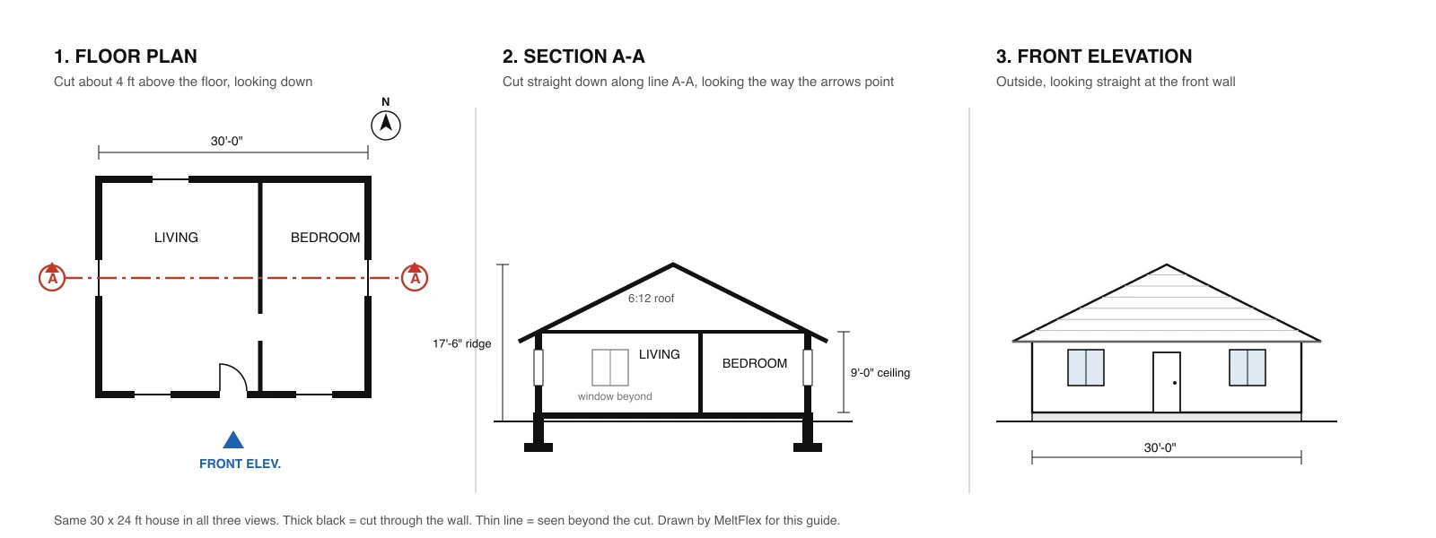
A floor plan is a horizontal cut through one level, usually about 4 feet above the floor, looking down: walls, doors with their swings, windows, stairs, fixtures and the dimensions that place every wall. It is the drawing everything else is coordinated to, which is why it is sheet A-101 and not A-501.
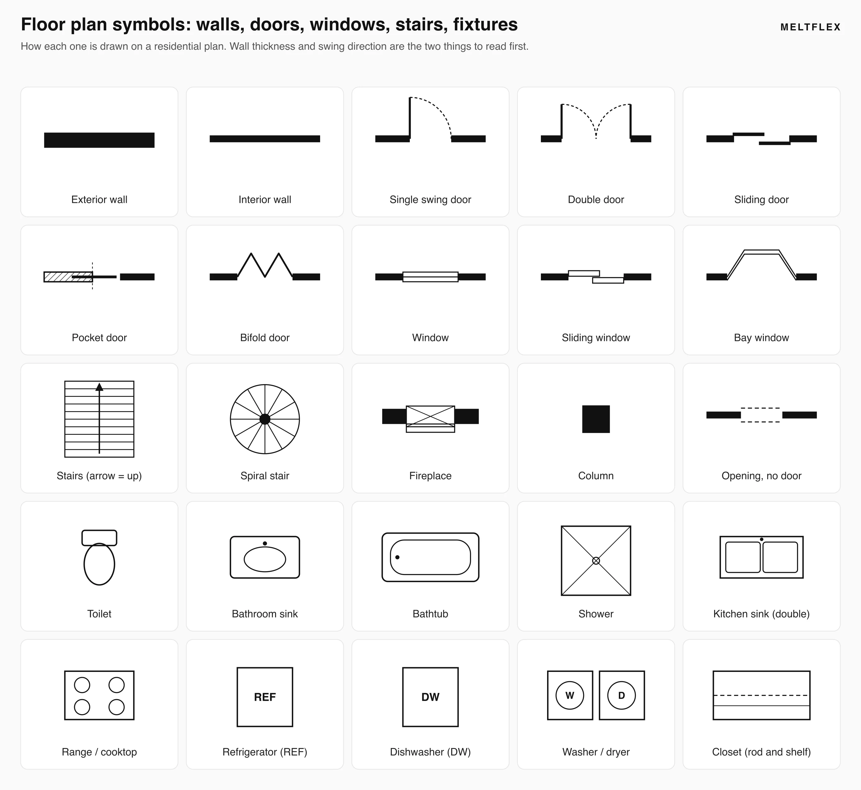
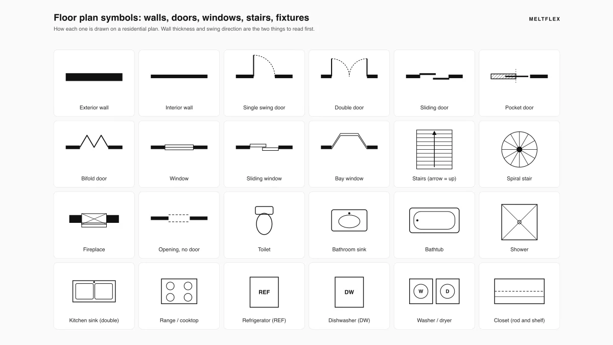
The symbols a floor plan is built from: walls, doors, windows, stairs and fixtures. We drew this legend as vector artwork for our floor plan symbols guide.
Reading the walls, door arcs and window breaks is its own skill, and the symbols guide covers it symbol by symbol, including how to read a whole floor plan. If you want to draw one yourself, start with how to draw a floor plan and check your room sizes against our floor plan examples with dimensions.
Elevation (elevation view)
An elevation is a flat, head-on view of one face of the building, with no perspective: every window, door, material change and height is drawn at its true size, so it can be measured. A house usually gets four exterior elevations, named by direction (north elevation) or by side (front, rear, left, right). Interior elevations do the same for single walls inside, mostly in kitchens and bathrooms, where cabinet heights and tile have to be drawn.
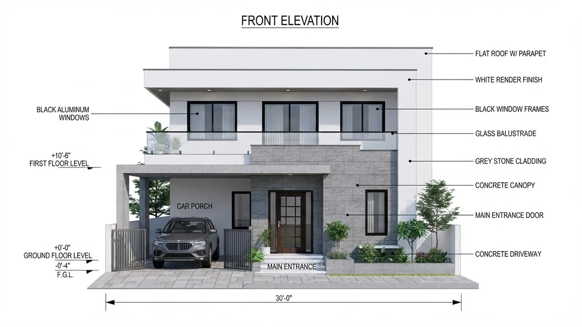
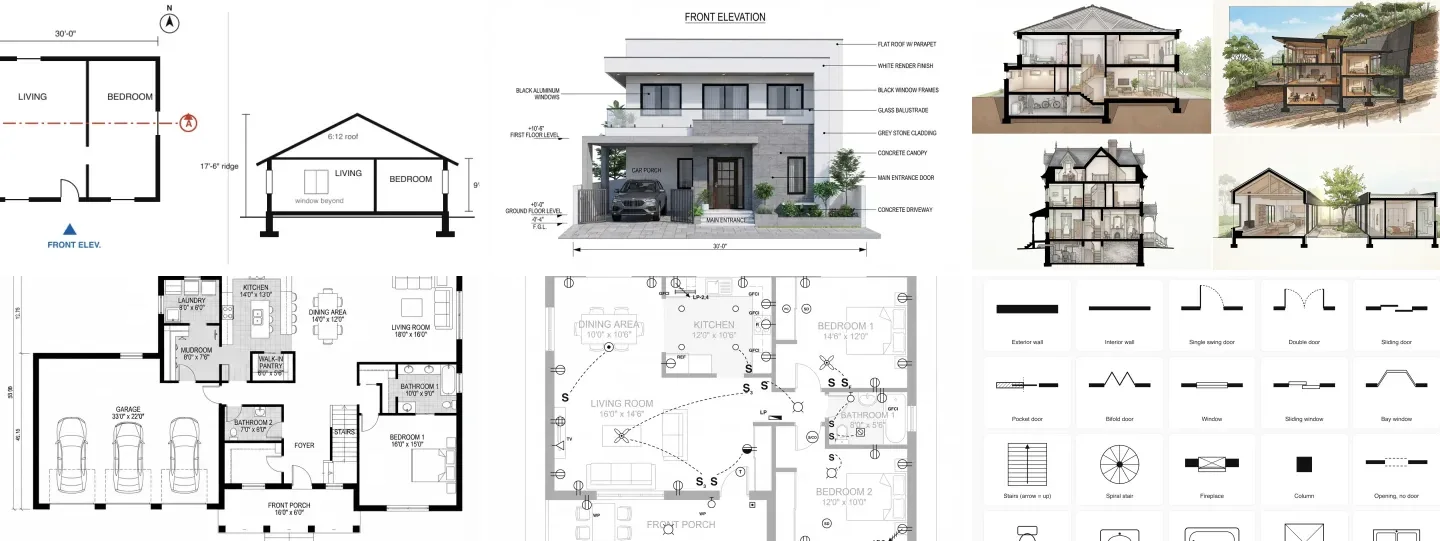
An annotated front elevation, generated with one of the prompts in our house elevation design prompts post. The format is right: level markers, material callouts, an overall dimension. Treat the numbers on any AI elevation as decoration until someone checks them.
The phrase “elevation view” comes from orthographic projection: a plan view looks down, an elevation view looks horizontally. People searching for elevation design are often after the look of the front of a house rather than a drawing, which is a design question; the elevation prompts post covers that side.
Section drawing (building section and wall section)
A section drawing is an imaginary vertical cut through the building, drawn as if you sliced it open and looked at the cut face: floors, walls, ceilings, roof and foundation in profile, with the heights between them. Anything the cut passes through is drawn with a heavy line or solid fill; anything you see beyond the cut is drawn thin. That convention is the single most useful thing to know when reading one, and it is what the diagram at the top of this page shows.
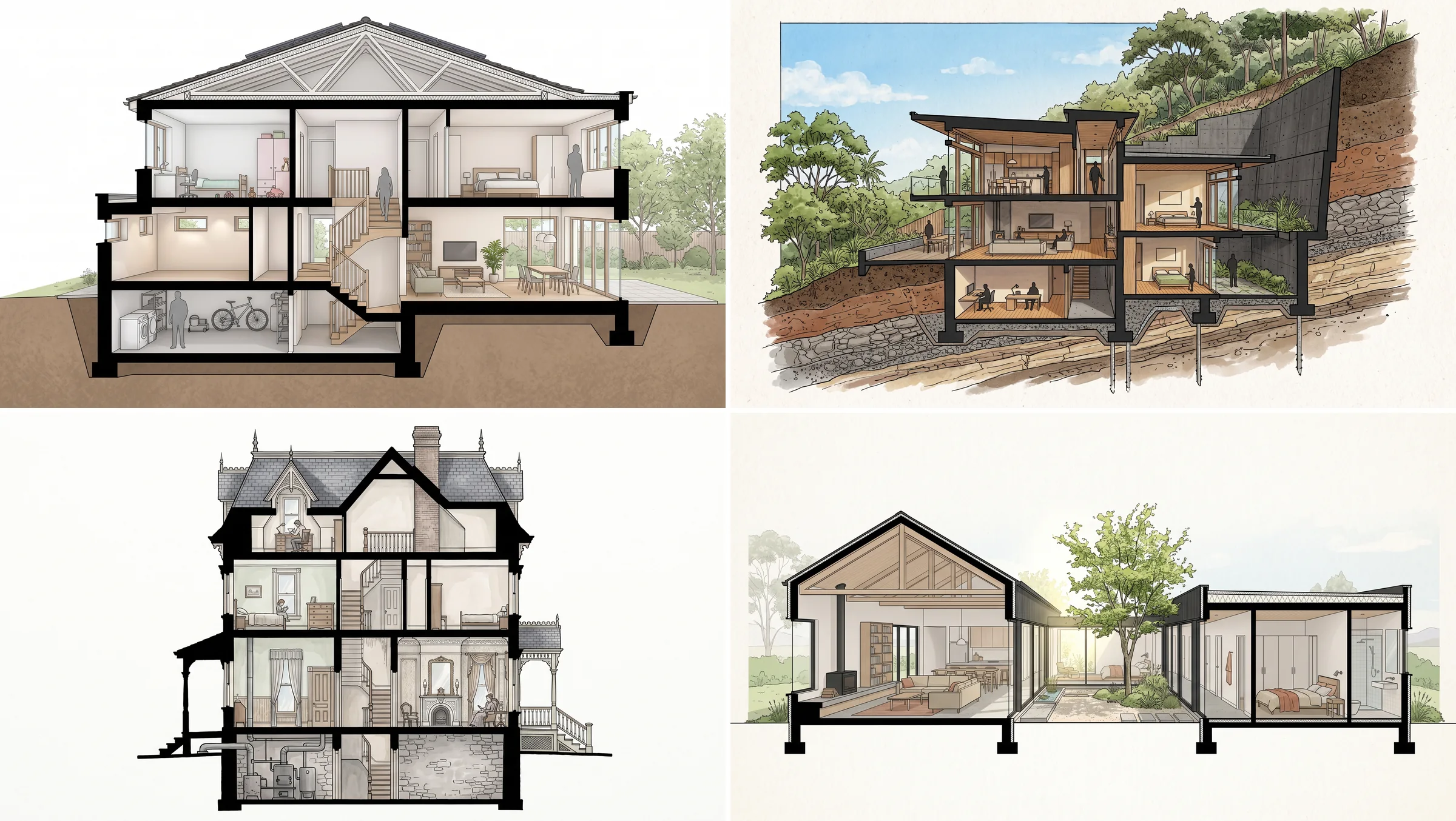
Section perspectives from our house cross section prompts post. These are presentation drawings: they explain a house well, but a construction section is flat, to scale and dimensioned.
A building section cuts through the whole house, usually through the stair or the tallest space, to show how the levels relate. A wall section zooms into one exterior wall from footing to roof at a larger scale and names every layer: siding, sheathing, studs, insulation, drywall, the floor and roof framing. Details then go one step further and draw individual joints. Building sections are also where you check the numbers that the code cares about, such as ceiling heights and stair rise and run.
Reflected ceiling plan (RCP)
A reflected ceiling plan shows the ceiling as if a mirror on the floor reflected it up to you, so it lines up exactly with the floor plan underneath instead of appearing flipped, as it would if you lay on the floor and looked up. It carries ceiling heights and materials, soffits and bulkheads, light fixtures, ceiling fans, smoke alarms, sprinkler heads and supply diffusers.
On a house the RCP is often merged with the lighting plan, which is why the switches and fixtures in our electrical plan symbols guide show up on it. On commercial interiors it is its own sheet, and it is where the architect, the electrical engineer and the mechanical engineer fight over the same square foot of ceiling. It also catches a code item that is easy to miss: the IRC requires a smoke alarm “In each sleeping room” (R314.3), and the RCP is usually where you would see whether one was drawn. Our AI test below missed exactly that.
Details
Details are enlarged drawings of how two parts of the building meet: a window head and sill, a stair nosing, a roof edge with its flashing, a footing, a deck ledger. They are drawn at 1 1/2 or 3 inches to the foot so every layer and fastener can be shown, and they are where most leaks and callbacks are prevented or caused. A detail is referenced from a plan or section by a small circle with two numbers: the detail number on top and the sheet number below.
Schedules
Schedules are tables that list every door, window, finish or fixture once, with its size, type, material and hardware, keyed to tags on the plans. A door tag on the floor plan says “104”; the door schedule says door 104 is 3′-0″ by 6′-8″, solid core, 20-minute rated, self-closing. That last part is not decoration: the IRC requires the door between an attached garage and the house to be solid wood or steel at least 1 3/8 inches thick, or 20-minute rated, and self-closing (R302.5.1). Schedules are where that requirement becomes a line someone can order from. For standard sizes see our standard door sizes guide.
Structural and MEP drawings
Structural drawings show the foundation, framing, beams and connections; MEP drawings show the mechanical (heating, cooling, ventilation), electrical and plumbing systems. On a larger project each is drawn by a licensed engineer; on many houses the electrical and plumbing layouts are simple enough that the designer draws them and the trades size the rest.
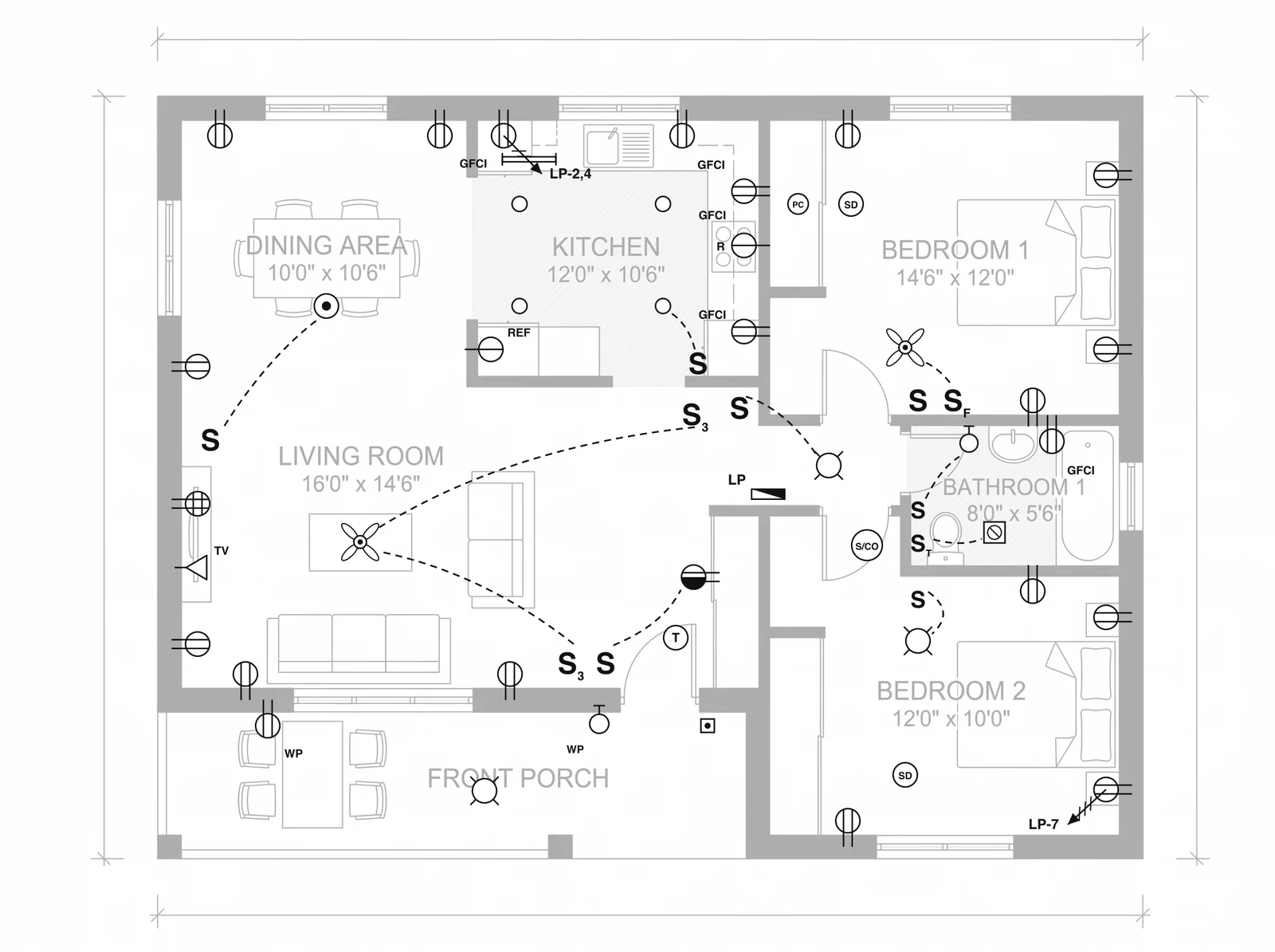
An electrical plan: the architectural plan is screened to grey and the electrical layer is drawn on top. Every symbol is decoded in our electrical plan symbols guide.
How is a set of architectural drawings organized?
Most US drawing sets follow the U.S. National CAD Standard: each sheet number starts with a discipline letter, then a digit for the type of drawing, then a sequence number, so A-201 means Architectural, elevations, first sheet. The standard (version 7 is current) combines the AIA CAD Layer Guidelines, the Construction Specifications Institute’s Uniform Drawing System and NIBS plotting guidelines, according to the National Institute of Building Sciences. The full text is sold, so the sheet type list below is taken from Archtoolbox’s summary of it, cross-checked against two university CAD standards that reproduce the same digits.
The discipline letters you will meet most on a house are G (general), C (civil), L (landscape), S (structural), A (architectural), I (interiors), M (mechanical), E (electrical) and P (plumbing). Two more are worth knowing because they surprise people: F is fire protection, and Z is reserved for contractor and shop drawings, which tells you something about where the standard thinks those belong.
The usual full-size sheet for construction drawings is ARCH D, 24 by 36 inches. That matters more than it sounds: a plan drawn at 1/4 inch to the foot on a 24 by 36 sheet and printed on 11 by 17 paper is no longer at any scale, and measuring it with a scale ruler will give you wrong numbers with total confidence.
What drawings are made at each design phase?
The same drawing types are redrawn at every phase with more detail: loose study drawings in schematic design, coordinated plans, elevations and sections in design development, and the full dimensioned set in construction documents. The AIA, which publishes the standard owner-architect contracts, describes five phases in Defining the architect’s basic services. Its own wording for the step most people mean when they say “architectural drawings”: “The construction document phase produces a set of drawings that include all pertinent information required for the contractor to price and build the project.”
The permit set is a subset of the construction documents, stamped where your state requires it. Section R106.1 of the IRC says the documents “shall be prepared by a registered design professional where required by the statutes of the jurisdiction in which the project is to be constructed,” which is a long way of saying that whether you need an architect or engineer depends on your state and town, not on the code. When the permit is issued, R106.3.1 requires one set to be stamped “REVIEWED FOR CODE COMPLIANCE” and kept on the job site. If you are designing your own house, our how to design a house guide covers the first two phases step by step.
Architectural vs construction vs working vs shop drawings: what is the difference?
Architectural drawings are the architect’s sheets at any stage. Construction drawings are the final coordinated set, architecture plus engineering, used for the permit and for building. Working drawings is an older name for construction drawings. Shop drawings are made by the contractor or a fabricator to show how one item will be built. Blueprints is the everyday word for construction drawings, left over from the cyanotype process that printed white lines on blue paper.
| Term | Who makes it | What it covers | Is it a contract document? |
|---|---|---|---|
| Architectural drawings | Architect or building designer | The architectural sheets, at any phase | Only as part of the CD set |
| Construction drawings (construction documents) | Architect plus engineers | The full coordinated set with specifications | Yes |
| Working drawings | Same as construction drawings | Older and academic name for the same set | Yes |
| Blueprints | Same as construction drawings | Everyday name for printed construction drawings | Yes |
| Shop drawings | Contractor, subcontractor or fabricator | How one item will be made and installed: steel, trusses, cabinets, windows | No, under AIA A201 |
| Record drawings (as-builts) | Contractor marks up; architect may compile | What was actually built, with field changes | No, a record |
- By
- Architect or designer
- Covers
- Architectural sheets, any phase
- Contract?
- Only in the CD set
- By
- Architect plus engineers
- Covers
- The full coordinated set
- Contract?
- Yes
- By
- Same as construction drawings
- Covers
- Older name, same set
- Contract?
- Yes
- By
- Same as construction drawings
- Covers
- Everyday name, printed set
- Contract?
- Yes
- By
- Contractor or fabricator
- Covers
- How one item is made
- Contract?
- No, under AIA A201
- By
- Contractor marks up
- Covers
- What was actually built
- Contract?
- No, a record
The shop drawing line is the one that causes real arguments. The AIA’s general conditions, A201, define shop drawings in Section 3.12.1 as “drawings, diagrams, schedules and other data specially prepared for the Work by the Contractor or a Subcontractor” and state in 3.12.4 that shop drawings “are not Contract Documents.” The architect reviews them only against the design intent. So if the steel fabricator’s drawing and the architect’s detail disagree, the architect’s drawing is the contract. Our sister product TechDraw has a full guide to what shop drawings are and how fabricators make them.
As-built drawings work the same way in reverse. A201 asks the contractor to keep a set of the documents marked up with field changes “as a record of the Work as constructed,” and AIA documents generally avoid the phrase as-built drawings for that reason: the mark-ups come from the contractor, so an architect who compiles them into record drawings is relying on someone else’s notes about what is inside the walls. If you are trying to find the drawings of a house you already own, our guide on how to get the blueprints of your house lists where they are usually kept.
How do you read architectural drawings?
Read a set in a fixed order: the cover sheet and sheet index, then each sheet’s title block, then the scale and north arrow, then the floor plans, and only then follow the markers out to the elevations, sections and details. A detail read on its own tells you how two pieces meet but not where in the building they are; the plan and the markers give it that context.
- Cover sheet first. It has the sheet index, the project data (lot, zoning, area), the code edition the design follows, the abbreviation list and the symbol legend. Ten minutes here saves an hour later.
- Title block on every sheet. Bottom right or along the right edge: the sheet number, drawing titles, date and revision list. If the revision on your copy is not the latest one, stop and get the latest.
- Scale and north. Each drawing has its own scale under its title, so one sheet can hold a plan at 1/4 inch and a detail at 3 inches. Plans should have a north arrow; elevations are often named after the direction they face.
- The floor plan, walked through. Enter at the front door and walk the rooms. Then read the dimension strings: the outer string gives the overall size, the next one in locates wall centers or faces, and the segments must add up to the overall. If they do not, that is an error, not a rounding difference.
- Follow the markers. A section marker is a line with a circle at each end: the top number is the drawing number and the bottom one is the sheet, so 3 over A-301 means drawing 3 on sheet A-301. The arrows show which way you are looking. Elevation markers and detail callouts work the same way.
- Tags lead to schedules. A number in a hexagon, circle or box next to a door or window is a tag; look it up in the schedule for its size, type and hardware.
- Notes and specifications last. General notes and the written specifications say what the lines cannot: materials, standards, testing and who is responsible for what.
Lines carry meaning too. These conventions are shared by almost every US office, even when the exact pen widths differ:
The scales you will meet, with their ratios, so you can convert a measurement: 1/8 inch to the foot is 1:96, 1/4 inch is 1:48, 1/2 inch is 1:24, 3/4 inch is 1:16, 1 1/2 inches is 1:8 and 3 inches is 1:4. Engineer’s scales on site plans are written as 1 inch = 10, 20 or 30 feet, which is 1:120, 1:240 and 1:360.
If you would rather watch someone read a real set, Tom Stephenson, a construction professor who wrote a textbook on reading housing drawings, has a lesson series built on one house. This 31 minute lesson reads its basement plan: the drawing set overview, foundation plan, dimensions and symbols, line types, beams, joist runs and how the loads travel down. Earlier lessons in the same series cover the site plan and the elevations.

Can AI make or read architectural drawings?
Not yet in a way you can build from. In our test on November 3, 2026, AI produced a floor plan, an elevation, a ceiling plan and a section that all looked right at a glance, and none of them survived a careful check: dimensions that do not add up, a code requirement left out, and one AI reviewer that invented a code violation. AI is genuinely useful earlier and later in the process: for trying layouts, and for flagging possible errors that a person then checks.
Here is what I did, so you can repeat it. The input was one of our own plans: a farmhouse drawn by our AI floor plan creator from the request “modern farmhouse, 4 bedrooms, i need a walk-in pantry and a mudroom coming in off the garage,” published in our gallery. I checked it myself at twice its size first, then gave it to two Google models with the same prompt, asking each to act as a plan checker at a US building department. Then I asked Nano Banana Pro, Google’s image model, to draw the front elevation, the reflected ceiling plan and a building section from the same plan.
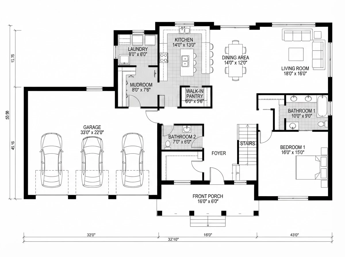
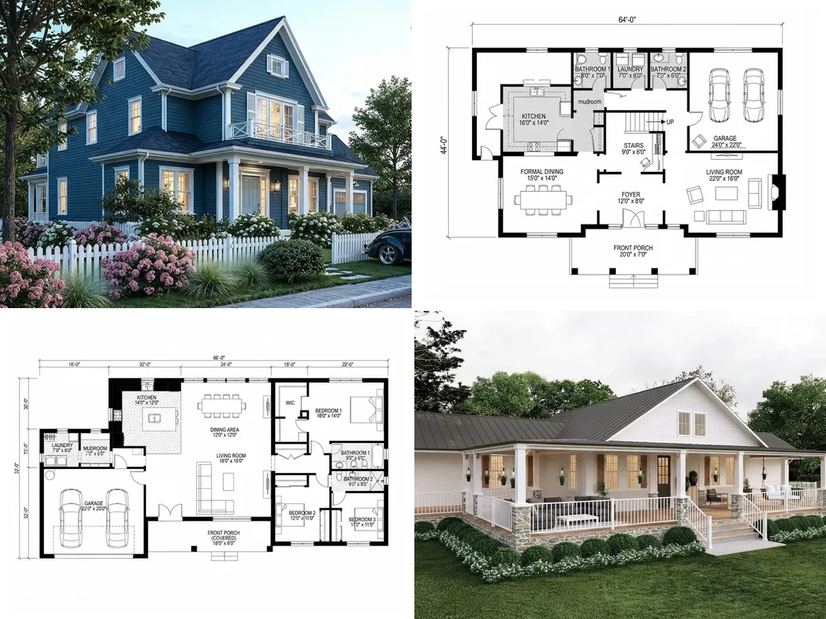
The test plan, drawn by our own AI floor plan creator. It reads like a real plan. Now add up the dimensions along the bottom.
What I found in our own AI floor plan
- The dimensions do not add up. The three segments along the bottom read 32′-0″, 16′-0″ and 43′-0″, which is 91 feet. The overall dimension under them says 32′-10″.
- The labels contradict the dimension strings. The garage is labeled 33′-0″ wide; the string below it says 32′-0″. The 43′-0″ segment sits under a bedroom labeled 16 feet wide.
- The side dimensions are not dimensions. The left side has numbers like 49.16 with no feet or inch marks, and the other two are too garbled to read with confidence.
- No scale, no north arrow, no title block, one unlabeled room off the foyer, and a door swing drawn inside a bathroom where the wall has no opening.
- Four bedrooms were asked for; one is drawn. There is a stair, so the rest may be upstairs, but no upper floor was produced.
We wrote about the same pattern in how to design a house: AI gets the arrangement of rooms right and the numbers wrong. Keep the arrangement and throw away the numbers.
What the AI plan checkers found, and what they made up
Gemini 4 Argon took 36 seconds and Gemini 3.5 Flash took 23. Both did the arithmetic correctly: both added 32, 16 and 43 to 91 feet and flagged the 32′-10″ overall, both caught the 33 against 32 foot garage, both said the drawing was not to a consistent scale, and both listed the missing scale, north arrow and title block. That is a genuinely useful first pass, done faster than I could do it.
Then they went too far. Both read the garbled side numbers as real numbers and did confident math on them. Flash described a door swing on the walk-in pantry that is not drawn and called the bathroom door a violation of “clear floor space standards” without naming one. Argon was worse, because it sounded the most authoritative: it reported that the only door into Bathroom 2 opens from the garage, that there was “no access to Bathroom 2 from the interior living space/Foyer,” and cited IRC R302.5.1. It is wrong twice. The plan shows a door from the foyer into that bathroom. And R302.5.1 reads: “Openings from a private garage directly into a room used for sleeping purposes shall not be permitted.” A bathroom is not a sleeping room; the code allows that door if it is solid or 20-minute rated and self-closing.
That is the failure that matters for anyone using AI to check drawings: the made-up finding was the most specific, best-formatted item in the report, with a code section attached.
What happened when AI drew the other sheets
- Front elevation: the best of the three. Three garage doors, the porch with its four posts and the front door all landed where the plan puts them. It also copied the impossible 91′-0″ overall width onto the elevation, so the error now appears on two sheets.
- Reflected ceiling plan: not a ceiling plan. It drew lights, fans and smoke alarms on top of the furnished floor plan, cars and beds included, added two legends that do not match each other, and kept every wrong dimension. Bedroom 1 got eight downlights and a fan but no smoke alarm, which the IRC requires “In each sleeping room” (R314.3).
- Building section: confident and incoherent. It wrote “18′-0″ TO ROOF PEAK” three times, pointing at three different heights, dropped the bedroom floor about two feet below the foyer although the plan shows no step, drew roof framing as vertical wall studs, and showed one wide garage door where the plan and its own elevation have three.
This matches what we saw when we turned a plan into a 3D model in our 2D floor plan to 3D model test: the layout comes through, and the AI fills the third dimension with guesses, such as a bathtub nobody drew. The best AI for technical drawings roundup covers the tools that do produce real dimensioned CAD output, which is a different and harder job.
What the profession says about AI drawing review
Automated review of real construction sets is arriving fast. On September 9, 2026, Buildcheck announced a $12 million Series A for software that reads 2D drawing sets and runs hundreds of checks for errors, coordination conflicts and code issues. Two articles published on October 29, 2026 by Nate Budde, chief legal officer of AIA Contract Documents, are the clearest statement of where responsibility sits. On the architect’s side, he writes: “The short answer is that the tool owns nothing.” He quotes the AIA’s own guidance on AI: “All AI-generated outputs must be reviewed and validated by qualified professionals.” And he notes that even Buildcheck has construction experts validate the output before a customer sees it.

Buildcheck’s homepage on November 3, 2026. Professional AI review tools exist for real drawing sets; the vendor still keeps people in the loop.
The companion piece for contractors makes the point our test illustrates: “A flag is not a proven error just because software generated it.” Our Argon result is exactly that: a flag that a person had to disprove.
Where AI helps with architectural drawings today
That last row is where our own tools fit, and I would rather you used them for that than for anything in the column on the right. The AI floor plan creator turns a written brief into a labeled plan for comparing layouts. Floor plan to 3D turns any plan, AI or hand drawn, into a 3D view so you can judge the rooms before a designer draws the real set. For the outside, exterior design restyles a photo of a house, which is the honest version of what most people want from an elevation drawing. If you are comparing tools, our AI floor plan generators comparison runs one brief through nine of them.
Our AI floor plan creator. Good for trying layouts; the plan it drew for this test is exactly why you should not build from one.
Who can make architectural drawings for a permit?
It depends on your state and your project: many states let a homeowner, a building designer or a drafter prepare drawings for a single-family house, while larger and commercial buildings need a licensed architect or engineer to seal them. The IRC leaves the question to local law: construction documents “shall be prepared by a registered design professional where required by the statutes of the jurisdiction” (R106.1). Structural work, such as removing a bearing wall or a long beam, usually needs an engineer even where the rest does not. Call your building department before you pay anyone to draw; they will tell you what they accept.
What the department will check is the same everywhere the IRC applies: R106.1.1 asks for documents “of sufficient clarity to indicate the location, nature and extent of the work proposed and show in detail that it will conform to the provisions of this code.” Every error in our AI test above would fail that sentence.
How we checked this, and what we could not verify
Code text is quoted from the 2021 International Residential Code, read on the ICC’s code site on November 3, 2026 (R106.1, R106.1.1, R106.2, R106.3.1, the R202 definition of construction documents, R302.5.1 and R314.3). Your state or town may have adopted a different edition or amendments. The sheet numbering comes from Archtoolbox’s summary of the U.S. National CAD Standard and two university CAD standards; we did not buy the NCS itself. The AIA A201 wording on shop drawings (3.12.1, 3.12.4) and record documents (3.11) was read in public copies of the form and AIA commentary, not in a purchased copy; check the edition in your own contract. Scales in the tables are common practice, not requirements.
The AI test was run once per model on November 3, 2026 with one plan; models change and a second run may differ. The test outputs are described in the text rather than shown, and every error listed was checked by me against the drawing at twice its size. The elevation, section and electrical images above come from our earlier guides and are labeled as AI-generated where they are.
Architectural drawings: FAQ
What are architectural drawings?
Architectural drawings are scaled drawings that describe a building: where it sits on the lot (site plan), how the rooms are laid out (floor plans), what the outside looks like (elevations), how it is put together vertically (sections) and how the pieces meet (details), plus schedules of doors, windows and finishes. At the end of design they are combined with the engineers’ sheets into the construction drawings used for the permit and for building.
What are the main types of architectural drawings?
The main types are the site plan, floor plans, roof plan, reflected ceiling plan, exterior and interior elevations, building and wall sections, details and schedules. A full construction set adds structural sheets and mechanical, electrical and plumbing (MEP) sheets drawn by engineers. On a US set each sheet number tells you the type: A-101 is an architectural plan, A-201 an elevation, A-301 a section and A-501 a detail sheet.
What is the difference between architectural drawings and construction drawings?
Architectural drawings are the architect’s own sheets, made at every stage from early sketches to the final set. Construction drawings are the finished set a contractor builds from and a building department reviews: the architectural sheets plus structural, mechanical, electrical and plumbing sheets, coordinated and drawn to scale. Every construction set contains architectural drawings, but not every architectural drawing is a construction drawing.
What are working drawings?
Working drawings is an older name for construction drawings: the fully dimensioned, scaled set that a builder works from on site. The term is still used in many offices and schools. It is not the same as shop drawings, which the contractor or a fabricator prepares to show how a specific item, such as a steel stair or a cabinet run, will be made and installed.
What is a reflected ceiling plan?
A reflected ceiling plan (RCP) shows the ceiling as if a mirror on the floor reflected it up to you, so it lines up exactly with the floor plan instead of appearing flipped. It shows ceiling heights and materials, soffits, light fixtures, fans, smoke alarms, sprinkler heads and air diffusers. On houses it is often combined with the lighting plan; on commercial jobs it is its own sheet.
What is the difference between a section and an elevation?
An elevation shows a wall from the outside or inside, looking straight at its surface: windows, doors, materials and heights. A section is a cut: an imaginary vertical slice through the building, so you see the floors, walls, ceilings and roof in profile and can read how tall each space is and how the structure stacks. Elevations show what the building looks like; sections show how it is built.
What scale are architectural drawings?
Residential floor plans in the US are usually drawn at 1/4 inch = 1 foot (1:48). Larger buildings use 1/8 inch = 1 foot (1:96). Site plans often use an engineer’s scale such as 1 inch = 20 feet. Enlarged kitchen, bath and stair plans go up to 1/2 inch = 1 foot, wall sections to 3/4 inch, and details to 1 1/2 or 3 inches = 1 foot. The scale is printed under each drawing title, and a set printed on smaller paper is no longer to scale.
Can AI create architectural drawings?
AI can draw a convincing floor plan, elevation or section in seconds, but in our November 2026 test none of the outputs could be built from. Our own AI floor plan had dimension strings that added up to 91 feet against a stated 32 feet 10 inches, and an image model asked to derive a ceiling plan left out the smoke alarm the code requires in the bedroom. AI is useful for early layouts and for flagging errors; a qualified person still has to draw, check and sign the set.
Sources
- International Code Council, 2021 International Residential Code, Chapter 1: R106.1 submittal documents, R106.1.1 information on construction documents, R106.2 site plan, R106.3.1 approval.
- 2021 IRC, Chapter 2 Definitions: construction documents, registered design professional, lot line.
- 2021 IRC, Chapter 3 Building Planning: R302.5.1 garage opening protection, R314.3 smoke alarm locations.
- National Institute of Building Sciences, United States National CAD Standard: version 7 and its components.
- Archtoolbox, Construction Document Sheet Numbers: discipline designators and sheet type digits.
- American Institute of Architects, Defining the architect’s basic services: the five design and construction phases.
- Nate Budde, AIA Contract Documents, When AI Reviews the Drawings, What Does the Architect Own? (October 29, 2026).
- Nate Budde, AIA Contract Documents, Does AI Drawing Review Change What Contractors are Responsible For? (October 29, 2026).
- AEC Magazine, Buildcheck raises $12m in Series A.
- Our own test, November 3, 2026: one plan from the MeltFlex AI floor plan creator, reviewed by Gemini 4 Argon and Gemini 3.5 Flash, and redrawn as an elevation, a reflected ceiling plan and a section by Nano Banana Pro (Gemini 3 Pro Image).
Keep reading
- Floor plan symbols: walls, doors, windows and fixtures, and how to read a floor plan.
- Electrical plan symbols: outlets, switches, lights and the reflected ceiling plan.
- How to get the blueprints of your house, from the builder, the county or a new survey.
- How to design a house, ten steps from budget to permit drawings.
- House cross section prompts and house elevation design prompts, for presentation drawings.
- What is BIM, the model behind most modern drawing sets, and how to connect ChatGPT to Archicad, one of the programs that draws them.