Electrical Plan Symbols: How to Read Outlets, Switches and Lights on a Floor Plan

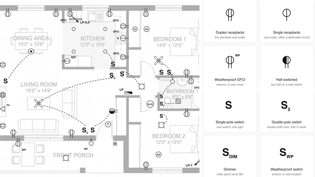
Electrical plan symbols are the shorthand that puts outlets, switches, lights and alarms onto a floor plan. A small circle with two parallel lines running to the wall is a duplex receptacle, the ordinary wall outlet. The letter S is a switch, S3 a three-way switch. A circle out in the room is a ceiling light, a small plain circle is a recessed downlight, a circle with SD is a smoke alarm, a triangle is a data or TV outlet, and a dashed curve says which switch controls which light. In the United States the conventions come from ANSI/NECA 100-2024, elsewhere from IEC 60617, and every drawing set still carries its own legend. Below are 48 symbols drawn one by one, the lines that connect them, the NEC spacing rules that decide where they go, and a real two-bedroom plan with the whole electrical layer drawn on it.
Our articles are still written by humans!
Get human written articles in your Google feed.
The cover: the electrical layer drawn over a plan from our own AI floor plan creator, beside the receptacle and switch symbols this guide starts with.
The short version
- Outlets: circle plus two lines to the wall = duplex. One line = single. Grid = quad. Half filled = one half on a switch. Letters add the type (GFCI, WP, TR, USB, R).
- Switches: always an S. S3 = three-way (pairs), S4 = four-way, SDIM = dimmer, SWP = weatherproof.
- Lights: circles in the room, not on the wall. Small plain circle = downlight, blades = fan, stem and bar = wall sconce.
- Everything else: circle with letters = device (SD, CO, T, J). Triangle = data or TV. Half-filled rectangle = the panel.
- Lines: dashed curve = switch leg (what controls what, not the cable route). Arrow with hash marks = home run to the panel.
- Placement: the NEC 6-foot rule, 24 inches on kitchen counters, 3 feet from a bathroom basin. Your local code edition decides.
Jump to: What they are · Symbols chart · Outlets · Switches · Lighting · Alarms and data · Lines · A real plan · NEC placement rules · US vs UK · Abbreviations · Mistakes · Draw your own · Sources · FAQ
FreeUpload plan or sketch · freeDraw my floor plan for freeDescribe the house, or upload a sketch, and MeltFlex draws a labelled 2D plan with room names and dimensions. Your first AI design is free, no card needed.
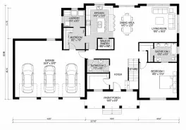
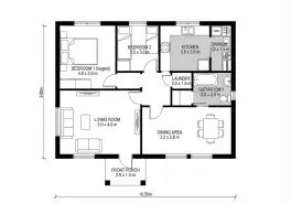
What are electrical plan symbols, and who decides what they look like?
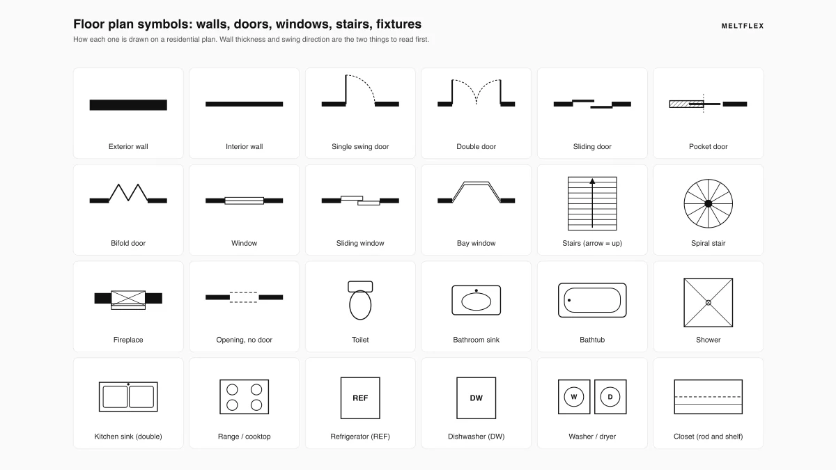
An electrical plan is a floor plan with a second layer on it: every receptacle, switch, light, fan, alarm, data jack and panel, placed where it will physically be. The symbols are small and abstract because they stand for devices on walls and ceilings, not objects on the floor, and the architecture underneath is usually printed in light grey so the electrical marks read on top. It is one sheet in a drawing set, next to the floor plan symbols for walls, doors and windows that it is drawn over.
Three different documents get called “electrical symbols”, and most of the confusion online comes from mixing them up. If you searched for a resistor or a capacitor, you want a schematic chart, not this page.
The US standard for plan symbols is ANSI/NECA 100, Symbols for Electrical Construction Drawings, published by the National Electrical Contractors Association with editions in 1999, 2006, 2013 and, most recently, 2024. Older guides, including the first version of our own floor plan symbols article, cite ANSI Y32.9, a 1972 ANSI standard. Y32.9 is where many of the shapes trace back to, but it is not the current reference. In practice no residential drawing follows either standard letter for letter: every architecture or engineering office has its own variations, and the legend on the sheet overrides any chart, including this one. What follows is the common core that nearly every US residential legend agrees on.
Electrical plan symbols chart: all 48 at a glance
This is the whole set in one table: the symbol’s name, how it is drawn on a US house plan, and what it means. Receptacles are circles with lines to the wall, switches are the letter S with a subscript, lights are circles out in the room, and devices are circles with letters. Each group is drawn in full, with notes, in the sections below.
What do outlet (receptacle) symbols look like on a floor plan?
The base symbol is a small circle with lines through it that run on to the wall. The lines point at the wall the outlet is mounted on, so on a plan the same symbol appears rotated four ways around a room. Two lines is a duplex receptacle, the standard two-socket outlet; one line is a single receptacle, usually on a dedicated circuit for one appliance; a grid of four lines is a quadruplex. Everything else is the duplex plus a modifier: a filled half, a square around it, or letters beside it.
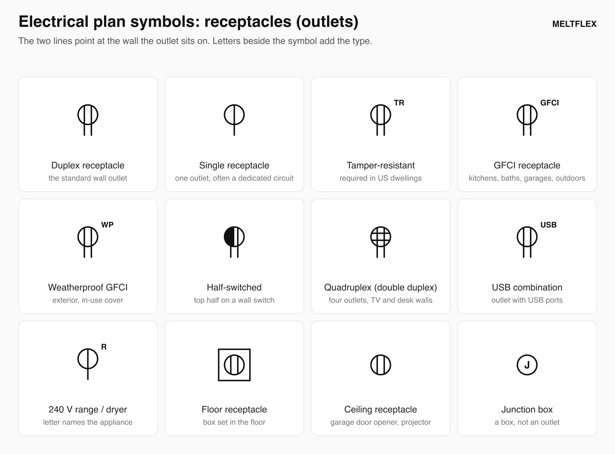
The twelve receptacle symbols a US house plan uses. The letters are what change the meaning; the circle stays the same.
Three of the letters are code requirements rather than preferences, which is why they appear on almost every current plan:
- GFCI (ground-fault circuit interrupter) protects people from shock. The 2023 National Electrical Code, section 210.8(A), requires it for dwelling receptacles in bathrooms, garages, outdoors, crawl spaces, basements, laundry areas, within 6 feet of any sink, bathtub or shower, and now for every 125 to 250 volt receptacle in a kitchen, not only those serving the counter. That last change is why newer plans mark the range and dishwasher outlets GFCI as well.
- TR (tamper-resistant) has shutters that stop a child pushing a key into the slot. NEC 406.12 requires it for essentially all 15 and 20 amp receptacles in homes, so many legends leave TR off and state it once in the notes.
- WP (weatherproof) means an in-use cover outdoors. Exterior receptacles also need GFCI, so the symbol often carries both.
The half-filled duplex is the one people most often misread. It is not a damaged or half-installed outlet; it means one of the two sockets is switched, usually so a floor lamp can be turned on from the door. The 240 volt outlets for a range, dryer or EV charger use a single receptacle with a letter (R, D, EV) and are almost always on their own circuit. A junction box, a circle with J, is not an outlet at all: it is a box where conductors are joined or where a hardwired device like a dishwasher, disposal or under-cabinet light connects.
What do light switch symbols look like?
Every switch is the letter S, drawn next to the wall where the switch box goes, usually just inside a door on the latch side, so it is not hidden behind the open door; the subscript tells you what kind. The wall a pocket door slides into cannot take a switch at all, one of the trade-offs in our standard door sizes guide. Height is not on the plan: 48 inches to the top of the box is the common US default, and anything intended to be accessible must fall inside the 15 to 48 inch reach range of the 2010 ADA Standards, section 308.
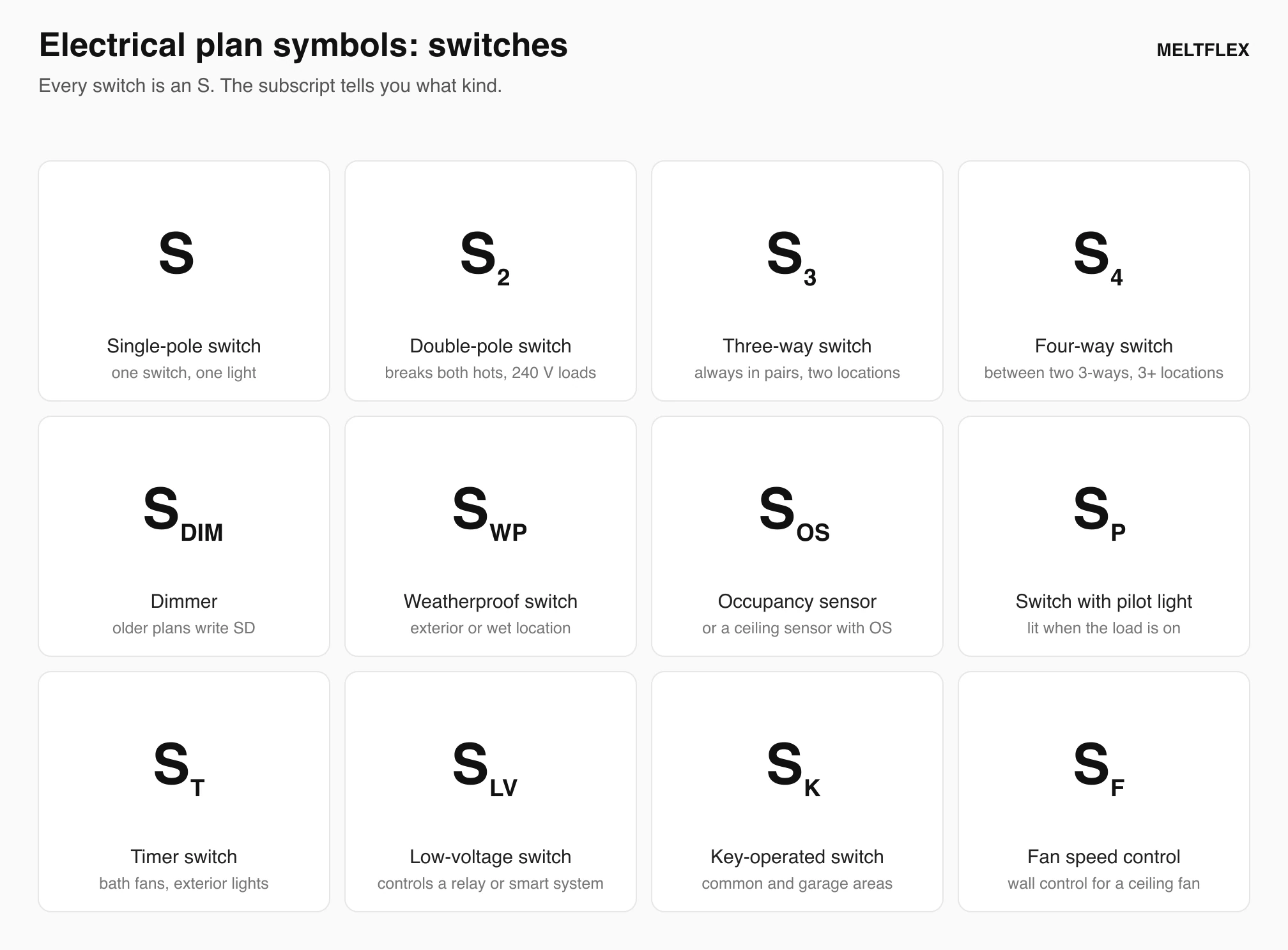
Twelve switch symbols. The three that matter on almost every house plan are S, S3 and SDIM.
The pair people get wrong is S3 and S4. A three-way switch never appears alone: two S3 switches at two locations, typically the two ends of a hall or the top and bottom of a stair, both control the same light. On stairs it is not optional: the IRC (R303.7.1) wants a wall switch at each floor level for the stair light once a stair has six or more risers, which our stair dimensions guide counts out. If you see a single S3 on a plan, the drawing is missing its partner or the legend uses S3 for something else. Add a third location and a four-way (S4) goes between the two three-ways; there is no “S5”, you add more four-ways. The naming trips up anyone who has worked with British drawings, where the three-way is called a two-way switch and the four-way an intermediate.
One genuine trap: SD. On many older US plans S with a subscript D was a dimmer. On current plans SD in a circle is a smoke detector. The position settles it (a dimmer is on the wall at a door, a smoke alarm is on the ceiling in the middle of a room), and good legends now write SDIM for the dimmer to kill the ambiguity. We drew ours that way.
What do lighting, fan and ceiling symbols mean?
Lights are drawn where they are on the ceiling, so they sit out in the room rather than on the wall line. A ceiling fixture is a circle, often with four short ticks or a cross through it; a recessed downlight is a small plain circle, drawn to the size of the trim on commercial sets; a pendant has a dot or letter inside; a wall sconce is a circle with a stem and bar that mark the wall it hangs on. On larger projects the lighting gets its own sheet, a reflected ceiling plan, which draws the ceiling as if the floor were a mirror, and the ceiling heights, soffits and beams appear with the lights.
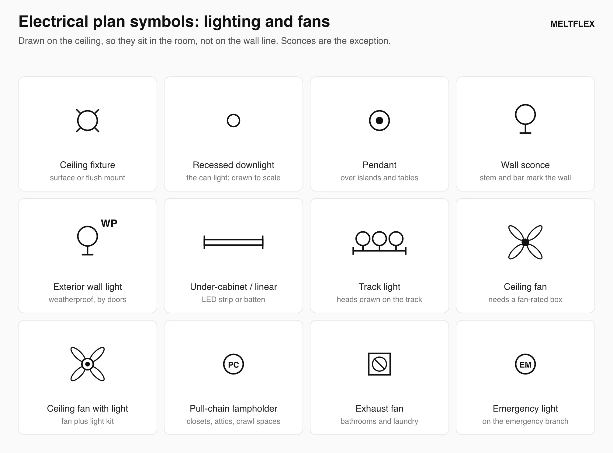
Lighting and fan symbols. Everything except the two wall lights is on the ceiling.
Two details on the lighting layer carry more weight than they look. A ceiling fan symbol means the box above it must be listed for fan support (NEC 314.27(C)); an ordinary light box is not rated for a heavy, vibrating load, and drawing a fan where the builder priced a light is how people end up paying for a retrofit brace. And a living room with no ceiling light is legal: NEC 210.70(A)(1) lets a habitable room other than a kitchen or bathroom use a wall switch controlling a receptacle instead of a lighting outlet, which is exactly what the half-filled outlet symbol is for. If you want an actual layered lighting scheme rather than one fixture per room, our room lighting guide covers what each layer is for.
What are the symbols for smoke alarms, thermostats, data and the panel?
The last group follows two simple rules. Circles with letters are devices: SD smoke, CO carbon monoxide, S/CO a combination unit, T thermostat, CH door chime, J junction box, SP speaker. Triangles are low-voltage outlets for data, phone and TV coax, with a stem to the wall like a receptacle. The panelboard is a rectangle, half filled for a power panel, labelled with its name (LP, PP, or just PANEL) so circuit numbers elsewhere on the sheet can point back to it.
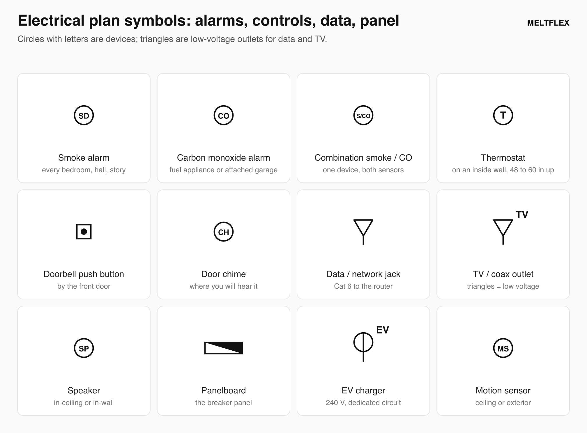
Alarms, controls, low-voltage outlets and the panel. The smoke and CO symbols are the ones to check first on any plan you are asked to sign off.
The alarm symbols are the part of an electrical plan worth checking even if you never intend to touch a wire. The International Residential Code (R314.3) requires a smoke alarm in each sleeping room, outside each separate sleeping area in the immediate vicinity of the bedrooms, and on every story including basements, all interconnected so one sounding sets off the rest. R315 adds carbon monoxide alarms outside the sleeping areas in homes with a fuel-burning appliance or an attached garage. Count the SD circles against the bedrooms. The NFPA’s analysis of electrical home fires found US fire departments responding to an average of 32,620 fires a year involving electrical distribution and lighting equipment in 2015 to 2019, causing 430 deaths a year, and the single most common room of origin was the bedroom, at 16 percent. It is the room where a missing SD circle matters most.
What do the lines between the symbols mean?
A dashed curve from a switch to a light is a switch leg: it shows which switch controls which fixture, not where the cable runs. A solid line between devices is a circuit run, an arrow with short hash marks is a home run back to the panel labelled with the panel and circuit number (LP-3,5), and a small number beside a device is its circuit. The symbols say what; the lines say what controls what and which circuit.
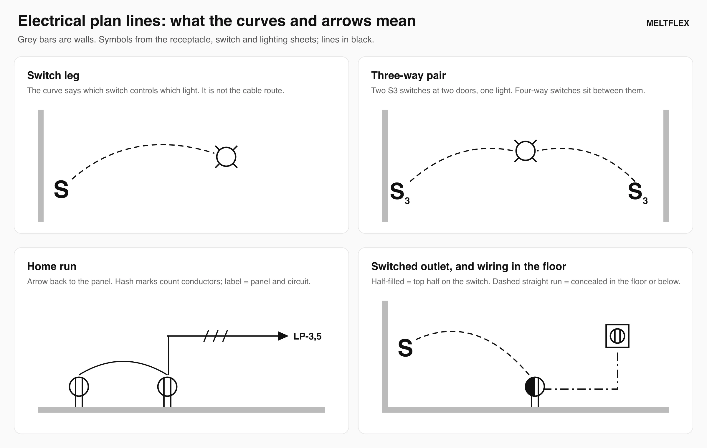
The four line conventions on a residential electrical plan. Grey bars are walls.
- Switch leg. A curve, usually dashed on house plans, from a switch to the light, fan or switched outlet it controls. It is a statement of control, not a cable route: the electrician decides the route. Curves are drawn curved precisely so nobody mistakes them for a wall-to-wall wire path.
- Circuit run. A solid line between devices on the same circuit, drawn on fuller sets. Solid usually means concealed in the wall or ceiling; a dashed straight run means concealed in the floor or below it. Check the legend: offices disagree on this one.
- Home run. An arrow from the last device on a circuit pointing roughly toward the panel, labelled with the panel and circuit number (LP-3,5 is circuits 3 and 5 on panel LP). Short hash marks across the line count the conductors when there are more than the default two; many offices draw the neutral longer and the ground with a different mark.
- Numbers and letters beside a device. A small number next to a receptacle or light is its circuit; a lowercase letter next to several lights groups them on one switch. A mounting height like +42″ next to a receptacle overrides the default.
What does a real residential electrical plan look like?
A residential electrical plan is the house plan printed in light grey with the electrical layer on top in black: receptacles every few feet along the walls, switches just inside each door, lights and fans out in the rooms, dashed curves from switches to what they control, smoke alarms in the bedrooms and hall, and home-run arrows to the panel. Charts only get you so far, so we drew a complete one on a real plan. The base is a two-bedroom, one-bath cottage with a front porch that our AI floor plan creator drew for its own showcase: a concept plan with room names and sizes and furniture, and, deliberately, no electrical layer at all. We screened the architecture back to grey the way an electrical sheet does, then placed every device by hand against the 2023 NEC.
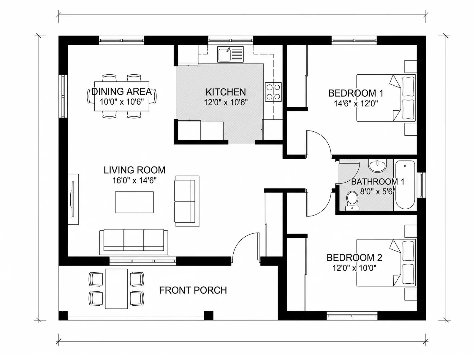
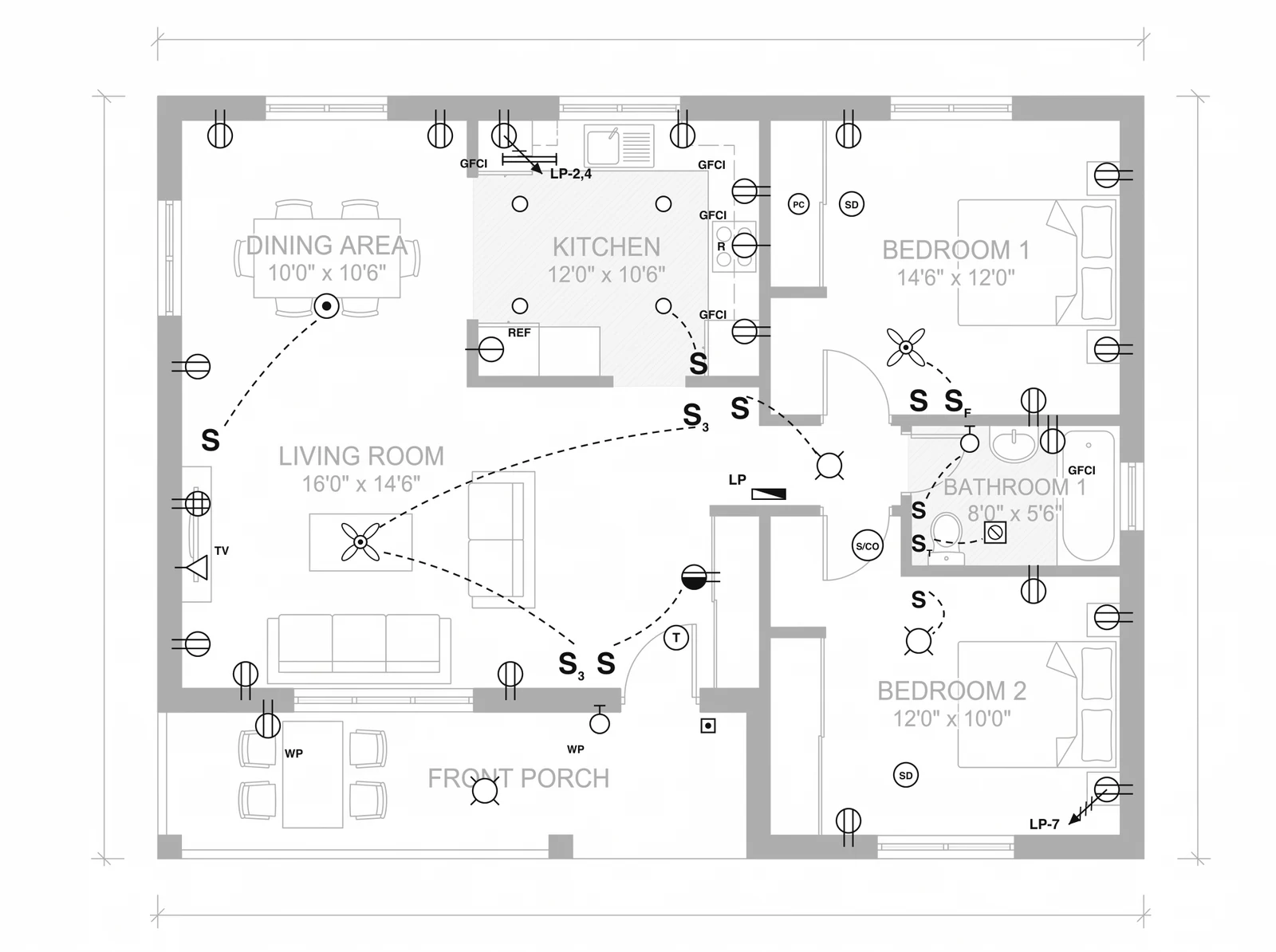
Room by room, this is what the layer says and the rule behind each choice:
Three things we did not expect when we drew it, and all three are worth knowing before you put an electrical layer on any plan, AI-made or not:
- The plan is not to scale, so the 6-foot rule cannot be checked with a ruler. Measured in pixels, the bathroom’s 8-foot width and the main bedroom’s 14½-foot width come out at scales about 13 percent apart. A concept plan’s written dimensions are the truth and the drawing is a sketch of them. We spaced the receptacles by the labels, and you should do the same on any plan that is not a scaled construction drawing.
- The obvious spot for the panel is illegal. The coat closet off the hall looks like the natural place for the breaker panel. NEC 240.24(D) prohibits overcurrent devices in clothes closets, so the panel went on the hall wall instead. Plans drawn without the electrical layer in mind rarely leave a good legal spot for it.
- The furniture moved the outlets more than the code did. The 6-foot rule alone would have put a receptacle behind the middle of the sofa and none at either nightstand. That is legal and useless. This is the reason to have the furniture on the plan before the electrical layer goes on; our bedroom layout guide and living room layout guide are the place to settle where things go first.
Where do outlets have to go? The NEC placement rules a plan should follow
A plan can use perfect symbols and still be wrong, because the symbols have to be in the right places. In most of the US the rulebook is the National Electrical Code, NFPA 70 (free to read online), which states adopt on their own schedule and often amend, so the edition your building department enforces may be 2017, 2020 or 2023. The residential placement rules are mostly in section 210.52 and have been stable for years, with a few notable changes in 2023.
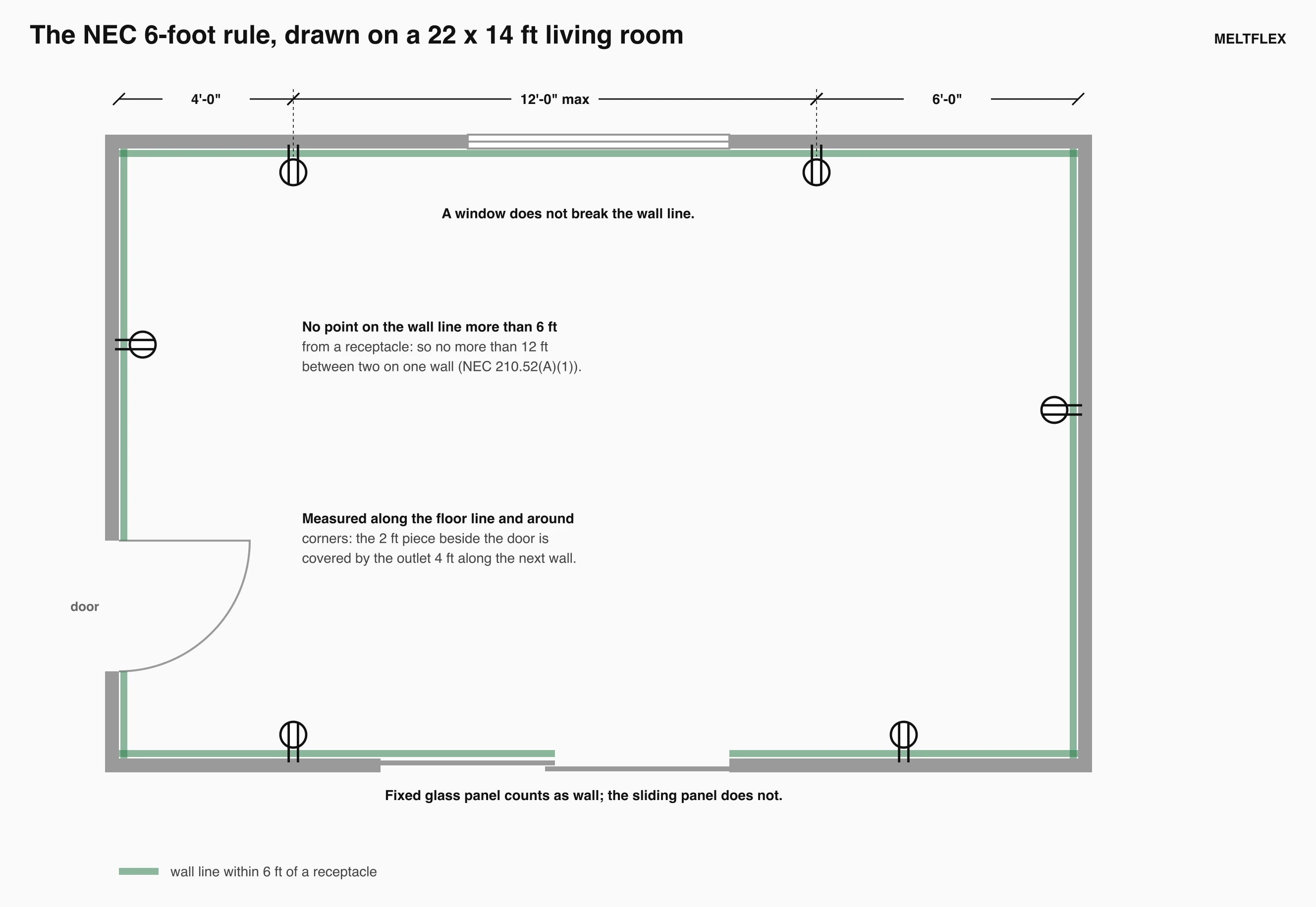
The 6-foot rule drawn out. Green is wall line within 6 feet of a receptacle; every piece of wall 2 feet or wider has to be green.
The general rule, 210.52(A), is the one in the drawing: in kitchens, family rooms, dining rooms, living rooms, bedrooms and similar rooms, no point measured horizontally along the floor line of any wall space may be more than 6 feet from a receptacle. Wall space is any stretch 2 feet or wider, measured around corners, broken only by doorways, fireplaces and fixed cabinets. Windows do not break it, and the fixed panel of a sliding glass door counts as wall. The result is the rule of thumb everyone quotes, no more than 12 feet between receptacles on a wall, which is only true for a straight wall with no corners involved.
The island change deserves its own sentence because plans drawn before 2023 still show it. The NFPA explains that the requirement to put receptacles in islands and peninsulas based on their size was removed, and replaced with a requirement to provide for a future one. So a plan that shows no outlet on the island is not necessarily wrong under the current code, and a plan that shows one is not required either. If you cook at the island, draw one anyway. For the rest of the kitchen planning, our kitchen layout guide covers the work zones the counter receptacles serve, and small bathroom layout dimensions covers where the basin, and so the 3-foot receptacle, can actually go.
Are electrical symbols the same in the US, the UK and Europe?
No. The US symbols above follow the NECA 100 practice. The UK, Europe and most of the world draw installation plans with symbols from IEC 60617, the international graphical symbols database. Same devices, a different drawing language.

The same seven devices in both conventions. IEC plans lean on semicircles and angled switch arms; US plans on circles and the letter S.
The rules behind the symbols differ as much as the shapes. A UK installation is designed to BS 7671, the IET Wiring Regulations, not the NEC; ring final circuits, fused spurs and bathroom zones have no US equivalent. UK guidance under Approved Document M puts switches and sockets between 450 and 1,200 mm above the floor in new homes, a band that has no single counterpart in the NEC. The vocabulary is where most transatlantic mistakes start:
If you are reading a plan from a country you did not train in, find the legend before you find the kitchen. Everything else follows from it.
Which electrical abbreviations appear on house plans?
Letters do most of the work on a residential electrical plan. These are the ones you will meet on house plans, as opposed to the unit abbreviations (V, A, W, Hz) that fill generic charts and rarely appear on a floor plan at all.
For the architectural abbreviations on the same sheet, REF and DW for the appliances themselves, WH for the water heater, the full list is in our floor plan symbols guide.
What do people get wrong when reading an electrical plan?
The six mistakes we see most: reading dashed switch legs as wire routes, trusting a generic chart over the sheet’s own legend, counting outlets instead of checking where they sit against the furniture, skipping the smoke and CO alarms, measuring a resized PDF, and assuming the wrong code edition. Each one, and what to do instead:
- Reading switch legs as wiring. The dashed curve from S to a light says what controls what. The cable can go anywhere. Do not plan a picture hook, shelf or TV mount around a curve on the drawing.
- Trusting a chart over the legend. Including this one. Every office varies; a circle with a cross is a ceiling light on one plan and a junction on another.
- Counting outlets instead of checking where they are. A room can pass the 6-foot rule and still put every receptacle behind the bed. Lay your furniture over the plan.
- Missing the alarms. Count SD circles against bedrooms and floors, and look for CO if there is gas or an attached garage. It takes thirty seconds.
- Measuring a PDF. A scanned, resized or AI-drawn plan does not match its stated scale. Space things by the written dimensions, not by the ruler.
- Assuming the code edition. A plan drawn to the 2017 NEC in a state still on 2017 is correct; the same plan in a 2023 state may not be. Ask which edition applies.
Most of these are layout problems before they are electrical ones, and the cheapest time to fix them is on paper. The TV above the fireplace question is a good example: the receptacle and data outlet go where the TV goes, so decide the TV height first.
How do you add an electrical layer to a floor plan?
If you are planning a renovation or briefing an electrician, you do not need CAD to produce a useful electrical layer. You need a plan with the furniture on it, the rules above, and an afternoon.
- Start from a plan with the furniture drawn in. If you do not have one, you can draw a floor plan by hand or generate a concept plan with the MeltFlex floor plan generator: pick the bedrooms, bathrooms, size and extras and it draws a labelled 2D plan with room sizes and furniture in about 20 seconds. Our floor plan examples with dimensions show what a usable base looks like. Print it light, or screen it grey.
- Receptacles by the 6-foot rule, then by the furniture. Walk every wall. Then add both sides of each bed, the TV wall, the desk (a home office layout needs more than one) and any floor lamp.
- Room-specific receptacles. Counters every 4 feet (GFCI), one by each basin, the hall, front and back outside, and the dedicated appliance outlets.
- Switches at the latch side of each door. Two doors into one room means a pair of S3s.
- Lights, fans and switch legs. Then draw the dashed curve from every switch to what it controls. A switched receptacle can replace a ceiling light outside kitchens and bathrooms.
- Alarms, data, the panel and a legend. Then give it to a licensed electrician. The layer you drew is a brief, not a permit set.
We should be clear about what our tools do and do not do here. The AI floor plan creator draws the architectural plan only; it does not place outlets, switches or lights, and we would not trust any generator that claims to produce a code-compliant electrical plan from a prompt. Where AI genuinely helps is the decision the electrical layer depends on: where the furniture goes. Upload the plan to floor plan to 3D and you can walk it as a furnished room, move the sofa and the bed, and only then decide where the receptacles belong. If you are choosing software to draw the layer itself, our comparison of the best floor plan software covers the apps you could draw it in (check for an electrical symbol library before you commit), and the AI floor plan prompts guide covers how to describe a plan so the generator draws the rooms you need.
How we made this guide
Every symbol here was drawn by hand as vector artwork for this article, following the common US practice of the ANSI/NECA 100 family and checked against published legends, including Archtoolbox’s symbol set; no symbol image was generated by AI. The worked example is a real output of the MeltFlex AI floor plan creator (its cottage showcase), with the electrical layer drawn over it by us against the 2023 NEC. Code sections are from the 2023 National Electrical Code and the International Residential Code; your jurisdiction may enforce an earlier edition or local amendments. Fire statistics are from the NFPA report Home Fires Caused by Electrical Distribution and Lighting Equipment (Richard Campbell, February 2022). We are not electricians: this is a guide to reading and briefing a plan, and any electrical work should be designed and installed by a licensed professional under a permit. We make the floor plan tools linked above; the reading advice is what we would give if we did not.
Sources
- ANSI/NECA 100-2024, Symbols for Electrical Construction Drawings: the current US standard for plan symbols; editions 1999, 2006, 2013, 2024.
- NFPA 70, National Electrical Code, 2023 edition (free access): 210.8(A) GFCI, 210.12 AFCI, 210.52 receptacle placement, 210.70 lighting outlets, 240.24 panel location, 314.27(C) fan boxes, 406.12 tamper-resistant receptacles.
- NFPA, Kitchen Island and Peninsula Receptacle Outlets and the NEC (18 January 2023): the 2023 removal of the island receptacle requirement and the future-provision rule.
- ICC, 2021 International Residential Code, chapter 3: R303.7 stair lighting switches, R314 smoke alarms, R315 carbon monoxide alarms.
- NFPA, Home Fires Caused by Electrical Distribution and Lighting Equipment (Richard Campbell, February 2022): 32,620 fires, 430 deaths a year in 2015 to 2019; bedroom the leading room of origin at 16 percent.
- U.S. Access Board, 2010 ADA Standards, section 308: 15 to 48 inch reach range for switches and controls.
- IEC 60617, Graphical symbols for diagrams (online database): the international symbol set used on UK and European installation drawings.
- UK Government, Approved Document M: switches and sockets 450 to 1,200 mm above the floor in new dwellings.
- Archtoolbox, Electrical Plan Symbols: the published legend we checked our receptacle, switch and lighting shapes against.
- Our own drawing: the electrical layer in this guide, drawn over the MeltFlex AI floor plan creator’s cottage showcase plan on 26 September 2026; the 13 percent scale difference was measured in pixels between walled rooms of known size.
Electrical plan symbols FAQ
What are the symbols on an electrical plan?
They are small abstract marks for devices, not drawings of the devices. A circle with two short parallel lines running to the wall is a duplex receptacle (a normal wall outlet); a circle with one line is a single receptacle; letters beside it add the type, GFCI, WP, TR or USB. Every switch is the letter S, with a subscript for the kind: S3 is a three-way, S4 a four-way, SDIM a dimmer. Ceiling lights are circles in the room, recessed downlights are small plain circles, fans are drawn with blades. Circles with letters are devices such as SD for a smoke alarm or T for a thermostat, triangles are data and TV outlets, and dashed curves link each switch to what it controls. The legend on the drawing always overrides a general chart.
What is the symbol for an outlet on a floor plan?
A small circle with two parallel lines through it that run on to the wall the outlet is mounted on. That is the duplex receptacle, the standard two-socket wall outlet in North America. One line instead of two is a single receptacle, often on a dedicated circuit for one appliance. A circle with a grid of four lines is a quadruplex. Half of the circle filled in means one of the two sockets is controlled by a wall switch. Letters next to the symbol give the type: GFCI for ground-fault protected, WP for weatherproof, TR for tamper-resistant, R or D for a 240 volt range or dryer outlet.
What is the symbol for a light switch on a floor plan?
The letter S, drawn just inside the room next to the door it serves. A plain S is a single-pole switch that controls a light from one place. A subscript changes the type: S3 is a three-way switch, always drawn as a pair so one light can be controlled from two places such as the two ends of a hall or the top and bottom of a stair; S4 is a four-way switch that goes between two three-ways for a third location; SDIM is a dimmer, SWP weatherproof, ST a timer. A dashed curve from the S to a light shows which fixture it controls. British drawings use a different symbol, a small circle with an angled arm, and call the three-way a two-way switch.
What does SD mean on an electrical plan?
Usually a smoke detector, drawn as a circle with SD inside. Be careful on older drawings, where SD next to an S was also used for a dimmer switch. The shape tells you which: a smoke alarm is a circle on the ceiling in the middle of a room or hall, a dimmer is the letter S on the wall at a door. Modern legends tend to write SDIM or SD with the D as a subscript for dimmers to avoid the clash, and CO or S/CO for carbon monoxide and combination alarms.
What is the difference between an electrical plan and a wiring diagram?
An electrical plan is a floor plan with the electrical devices placed where they will physically be: outlets on walls, lights on the ceiling, switches by the doors, plus curves showing which switch controls which light and arrows showing which circuit goes back to the panel. A wiring or schematic diagram ignores the building and shows how the components connect electrically, with resistors, contacts and conductors drawn using IEEE 315 or IEC 60617 schematic symbols. Homeowners, designers and permit reviewers read the plan; the electrician works out the wiring from it.
How far apart do outlets have to be under the NEC?
In living rooms, bedrooms and other habitable rooms, no point along the floor line of a wall may be more than 6 feet from a receptacle, which in practice means no more than 12 feet between two receptacles on the same wall, and every wall section 2 feet or wider counts. Kitchen countertops are stricter: no point along the counter wall more than 24 inches from a receptacle, and every counter section 12 inches or wider needs one. Bathrooms need at least one within 3 feet of each basin. Hallways 10 feet or longer need one. Your jurisdiction may adopt an older edition or local amendments, so check with the building department.
Do electrical symbols differ between the US and the UK?
Yes. US drawings follow the NECA 100 practice: circles with lines for receptacles and the letter S for switches. UK and European drawings follow IEC 60617: a socket outlet is a semicircle on a baseline with a stroke for each outlet, a one-way switch is a small circle with an angled arm ending in a tick, a light is a circle with a cross. The vocabulary differs too: receptacle and socket outlet, GFCI and RCD, AFCI and AFDD, panel and consumer unit, three-way and two-way switch. The electrical rules differ as well; UK installations follow BS 7671, not the NEC.
Can an AI floor plan generator draw the electrical plan?
Not reliably, and the MeltFlex floor plan creator does not try: it draws the architectural plan, the walls, doors, windows, room names and sizes, and leaves the electrical layer out on purpose. What an AI plan is good for is the step before the electrical layer: getting a plan with the rooms and furniture where you want them in about 20 seconds, so outlets can be placed where the bed, sofa and desk actually go. The electrical layer itself should be placed against the code your jurisdiction uses and checked by a licensed electrician before it goes to permit.